


38
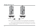
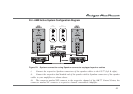
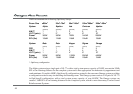
Scenario 2:
AM-77 CCE x 1
AM-77 x 2 (each AM-77 must be in Monoblock Power Amplifier Mode)
(see page 46 of AM-77 Manual).
Option cable Left channel RCA (Blue) Æ Left AM-77 Input 1 Left Channel
Option cable Right channel RCA (Red) Æ Right AM-77 Input 1 Left Channel
Attach the power cables to the amplifiers, however do not connect the power cables to the mains yet nor should
the amplifiers be switched on.
Route the mains cables so that they run cleanly and without sharp bends towards the power extension strip and
then attach the mains cables.
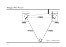
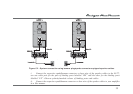
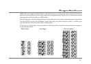
Speaker Connection
Scenario 1:
AM-77 CCE x 1
AM-77 x 1 (the AM-77 must be in Stereo Power Amplifier Mode)
Left speaker cable connector marked "HF/CCE" Æ AM-77 CCE 's Left Channel Speakon socket
Right speaker cable connector marked "HF/CCE" Æ AM-77 CCE 's Right Channel Speakon socket
Left speaker cable connector marked “LF/AM” Æ AM-77's Left channel Speakon socket
Right speaker cable connector marked “LF/AM” Æ AM-77's Right channel Speakon socket