


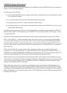

AVR400 Analogue Video Board
This is connected into the rest of the system via the HDMI board using CN301.The circuitry is shown on
sheet 13 of the schematic diagram.
The purposes of this PCB are:
(1) to switch between the various analogue video inputs (comprising 4 each composite and s-video
and 3 component video)
(2) to route the chosen video signal to the HDMI board for processing
(3) to provide one set of zone 1 video component video outputs
(4) to provide one zone 2 video output (composite video, with its own OSD) from any of the 4 com-
posite video signal inputs.
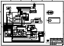
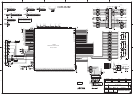
The PCBs power supplies are +9VV and +5VV, generated from the three-terminal regulators IC88 and
IC89 from the system’s +15VA supply on pin 1 of CN301. Pin 2 carries the system’s -15VA supply – this is
unused on this PCB.
Note that all video inputs are terminated with 75ohm resistors to ground close to the actual sockets.
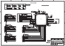
IC81 is a JRC NJW1321 – a wide bandwidth video switch with 4 inputs, 2 outputs and a 6dB amplier.
It is used to select between the 4 composite and 4 s-video inputs routed to the HDMI board and also
to output any one of the 4 composite video inputs to the On-Screen Display Controller IC83. IC81 runs
from the +9VV supply, consuming about 85mA so it gets quite hot. It is controlled by i2C commands on
pins 15 and 16.
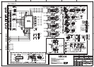
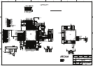
IC82 is also an NJW1321. It selects between the 3 component video inputs and its fourth input is
unused. Its Y, Cr, Cb outputs and the Y, C and CVBS outputs of IC81 are then AC coupled to IC84 – an
NJM2566 6 way video amplier/lter with 6dB gain, powered from the +5VV rail. Its outputs are also AC
coupled and terminated with 75 ohm series resistors before being routed to CN301.
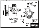
IC86 is a hex inverter used to bμFfer the 3V3 logic level OSD control signals from the HDMI board and
convert them to 5V level for IC83. This is a Sanyo LC74763 in a 30 pin SM package running from the +5VV
rail. It has two crystal oscillators X801 (17.734MHz) and X802 (14.318MHz) to provide composite video
outputs for both PAL and NTSC standards.
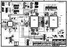
IC86’s video input signal is AC coupled to and bμFfered by the emitter follower Q802 before pin 18.
Similarly its output signal (which now includes an OSD) is bμFfered by the pnp transistor Q801 and AC
coupled to the video amplier/switch IC85 (NJM2244), used here purely as a composite video amplier/
lter with 6dB gain. Its AC coupled output to the Z 2 OUT single phono socket JK85 is terminated with a
68 ohms series resistor.