


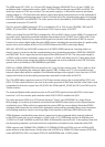
IC143 is the Cirrus Logic CS42548. It includes an SPDIF receiver, 2 channel ADC and 8 channel DAC. Only
one input (pin 43) of the SPDIF receiver is used; the others are grounded.
IC143 has +5V analogue supplies, locally decoupled to analogue ground by C721/722 for VA (pin 24)
and C703/704 for VARX (pin 41). The digital supply is also +5V, decoupled to digital ground by C705/706
(pin 5) and C750/756 (pin 51). The control port power VLC (pin 6) is 3V3, decoupled to digital ground by
C752/773 and the serial port power VLS (pin 53) is also +3V3, decoupled to digital ground by R726 and
C753/754. The 3V3 is generated from the +5V supply by the linear regulator IC148.
The system master audio clock is generated by IC143 on pin 55 whenever an SPDIF signal is present (i.e.
in all cases except when an HDMI multichannel signal in I2S is required to be processed or when using
the ADC). Although IC143 has no jitter rejection below 20kHz its master clock is kept clean from incom-
ing jitter by IC153. The PLL lter is located at pin 39. When SPDIF is not in use IC143 inputs its clock on
pin 59 – this can be 24.576 MHz from the crystal oscillator X701 associated with DSP1 when ADC mode is
engaged, or the recovered clock from the HDMI Board. This is switched by the 4 way change over mul-
tiplexer IC145 on pins 9, 10 and 11. IC145 also routes IC143’s recovered master clock or the HDMI master
clock to DSP1 on pins 5, 6 and 7.
Pins 1, 62, 63 and 64 receive the 24 bit serial audio data that has been processed by the DSPs.
The DAC’s 8 analogue outputs are in dierential mode, so making 16 output lines in total, from pins
20-23 and 26-37. These feed the post-DAC lters IC111-114, described above.
The main audio DSP is a Cirrus Logic CS 497024, IC141.This is a 300MIPS dual core 32 bit xed point DSP,
with 72 bit accumulators. The rst core is used for decoding standard and high denition audio formats
(Dolby, DTS etc) and the second is reserved for post processing such as bass management, delay and
room correction. The secondary DSP, IC142, is a Cirrus Logic CS49DV8, responsible for the Dolby Volume
processing. IC141 gets the 1.8V for its core from the 3-terminal regulator IC149. IC142 gets its 1.8V from
IC150. The 3V3_1 and 3V3_2 supplies for these regulators are generated on the Power Supply Board.
IC141, 142 and 143 communicate with the system microprocessor via an SPI bus. For IC141 and IC142
the chip select lines are on pin 6, the clock is on pin 126, the MISO line on pin 124 and the MOSI on
pin 123. For IC 143 the corresponding pins are pins 10, 7, 8 and 9. Note that the 3 chips receive data on
a common line but transmit to the μP on two separate ones (DSPDATA for both DSPs and D_OUT for
IC143).
IC141 communicates with its external memory via a 36 line data bus running at 150MHz. This is needed
when providing lip sync delay for audio accompanied by video. IC144 is a 200MHz 16Mbit SDRAM, or-
ganized as 512Kbits x 16bits x 2. It is powered from the board’s 3V3 line via 6 pins, with local decoupling
provided by C758-763.
The DSPs’ programs are stored in two external 3V3 SPI ash memory chips – IC106 (8Mbit) for IC141 and
IC107 (4Mbit) for IC142.
IC141 has two sets of I2S data inputs. DAI (pins 23, 24, 26, 27 for data, pin 29 for the system clock and pin
30 for the LR clock) is for up to 8 channels from the HDMI Board via connector WF104.
DA2 (pins 32 for the LR clock, 33 for system clock and 34 for data) is for audio from the codec IC143. This
includes bitstream SPDIF such as Dolby Digital, uncompressed two channel I2S audio decoded from
SPDIF and ADC generated I2S two channel audio.
The DSP master clock is input on pin 40 of IC141 from pin 9 of IC145 as noted earlier.