


the same manner as described above for RL902) then the L front input is routed to the low noise micro-
phone amplier IC903. This operates as two cascaded virtual earth ampliers, each with a voltage gain
of approximately 21 (R961/960 and then R965/962). Note the MIC line is biased at +6V via resistors R956,
R957 and R958. The amplied signal is output to the Input Board on pin 5 of CON101.
AVR400 Input Board Circuit Description
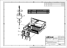
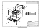
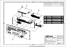
The Input Board comprises a 4 layer PCB; this is attached directly to the back panel via its various sock-
ets and to the heatsink by two steel brackets. It is positioned underneath the HDMI Board and above
the Main Board. 5 ribbon cable sockets connect it to the other 4 boards. CN71 connects it to a daughter
board containing two 9 Pin D socket connectors (an RS232 serial port and an iPod dock interface), plus
two 12V trigger sockets and 2 IR receiver sockets. Note some passive components are mounted on the
underside of the PCB.
The Input Board circuitry is shown on pages 2 – 5 of the schematic diagram.
Page 2 covers the analogue inputs, volume control and line level outputs.
Page 3 covers the SPDIF (digital) inputs, clock recovery, audio DSPs and the codec (stereo ADC plus
8-channel DAC).
Page 4 covers the system microprocessor and a slaved support microprocessor
Page 5 covers interfaces to the DAB/Ethernet module, and the boot loader microprocessor used to
update the system SW via USB.
Analogue inputs, volume control and outputs
IC101 is a Renesas R2A15218FP analogue multiplexer and volume control, with a gain range of +42 to
-95dB in 0.5dB steps. It is digitally controlled from the system microprocessor via the I2C bus on pins 49
and 50. A high logic signal on pin 51 enables the system mute. IC101 has +/- 7V supplies generated from
the +/-15V rails with the regulators IC102 and IC103.
All stereo external line level inputs using phono sockets are routed to IC101 via 100R/220pF low pass
CR lters. IC101 also handles the AUX-L, AUX-R and the (mono) MIC_SIGNAL setup microphone inputs
coming from the front panel, plus the internal stereo outputs from AM/FM tuners (TUN-L and TUN-R)
and the DAB/ethernet receiver (VENICE_L and VENICE_R). IC101 additionally switches two multichannel
signals - the 8 channel direct input and the outputs from the 8 post-DAC lters. Note that the +/- 7V
power supply limits the input signals to approximately 4V rms before overload occurs.
The post-DAC lters comprise 4 low noise NJM2068 dual op amps, running from the +/- 7V supplies.
One op amp is assigned to each channel and performs the dual functions of converting a dierential
input from the DAC to a single ended output, whilst simultaneously functioning as a three pole 50kHz
active lter.
The AM/FM tuner module’s outputs pass through the inductors L310 and L302 (providing 19kHz notch
and 38 kHz low pass ltering) and the shunt mute circuits formed by the 330R resistors R354/R369 and
the two halves of Q306 plus Q307.
IC101 has a xed level stereo output for Zone 2 (SUB_L and SUB_R) and a second one, adjustable from
0dB to -18dB in 6dB steps, for the AVR400’s analogue to digital converter (ADC_L and ADC_R).