


AVR350
6
Installation
Positioning the unit
<
Place the receiver on a level, rm surface.
<
Avoid placing the unit in direct sunlight or near sources of heat or damp.
<
Do not place the unit on top of a power amplier or other source of heat.
<
Ensure adequate ventilation. Do not place the unit in an enclosed space such as a bookcase
or closed cabinet unless there is good provision for ventilation. The receiver is designed to run
warm during normal operation.
<
Make sure the IR receiver in the centre of the front panel display is unobstructed, otherwise
this will impair the use of the remote control. If line-of-sight is impractical, an infrared remote
repeater can be used with the rear panel IR connector.
<
Do not place your record deck on top of this unit or any other unit which is mains supplied.
Record decks are very sensitive to the noise generated by mains power supplies which will be
heard as ‘hum’ if the record deck is too close.
Do not place any other component or item on top of the AVR350 as this may obstruct the ventilation
holes, causing the AVR350 to run hot. (The unit placed on top of the AVR350 would become hot, too.)
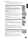
Notes on installing the AVR350
The inputs are named to make it easier to reference when connecting source components to the AVR350
(e.g., a DVD or VCR), but all inputs have the same circuitry. This means that there is no reason why you
should not connect a different device from that labelled to any of the inputs. For example, if you had two
DVD players and the AV input was not being used, then the second DVD player could be connected to
the AV input.
Cables
We recommend the use of high quality screened analogue, digital and video cables, since inferior
quality cables will degrade the overall quality of your system. Use only cables that are designed for the
particular application as other cables will have different impedance characteristics that will degrade
the performance of your system (for example, do not use cabling intended for audio use to carry video
signals). All cables should be kept as short as is practically possible.
Video and digital connections must be made with cables that are designed for this purpose, i.e., coaxial
cable with a 75Ω impedance. If substandard cables are used you may suffer from poor picture quality
such as ghost images and/or grainy picture quality (snow).
Speaker cables should be kept short to ensure efcient power transmission and avoid audible distortion.
It is good practice when connecting your equipment to ensure that the mains power supply cabling is
kept as far away as possible from your audio and video cables, as this will provide the best sound and
picture quality. Failure to do so may result in unwanted noise in the audio and video signals.
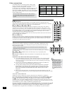
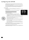
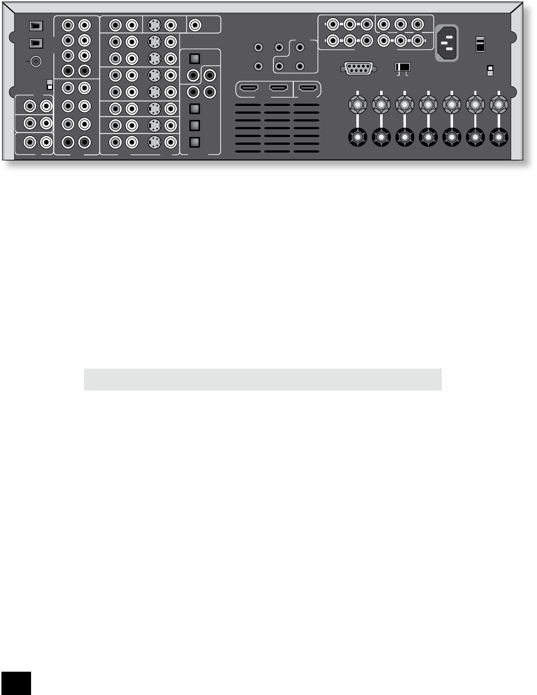
RS232 CONTROL
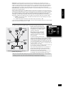
FR FL CEN RS LS RSB LSB
OUT
IN
VCR
OUT
IN
AUX
AV
SAT
DVD
S C
MON
OUT
ZONE
2
OUT
DIGITAL
OUT
CD
AVDVD
SAT
AUX
TAPE
R L
R
L
IN
IN
OUT
FR
RS
RSB
CEN
FL
LS
LSB
SUB
FR
RS
RSB
CEN
FL
LS
LSB
SUB
AC
INLET
AM
GND
(USA) 10K
(EU) 9K
AM STEP
GROUND
LIFT
GROUND
SPEAKER
IMPEDANCE
ZONE� 2
VIDEO
OUT
(ZONE 2)
SPEAKER
OUTPUTS
–
+
SATDVD
AV
DVD
OUT
SAT
HIGH QUALITY VIDEO IN
IN
ZONE2
IN
LOCAL
OUT
1/RGB 2/S-VID
+12V
TRIGGER
(Z1&Z2)
VIDEO TRIGGER
Y/G U/B V/R
REMOTE
HDMI IN HDMI OUT
Y/G U/B V/R
DIGITAL INVIDEOAUDIOMCH INCD
FM
OUTPUTS
TAPE
230
230
AC VOLTAGE
230V
120V
ANTENNA
8Ω
4Ω
The AVR350 rear panel