


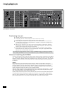
AVR350
10
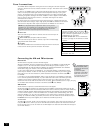
Zone 2 connections
The AVR350 allows independent routing and control of analogue audio and composite
video to a second room such as a kitchen, bedroom or lounge. This second room is known
as ‘Zone 2’.
For Zone 2, the AVR350 outputs a line-level audio signal taken from the stereo analogue
audio, and a composite video signal taken from the composite video input (for a given
source). The analogue inputs are required because there is no analogue-to-digital, DSP
processing or digital-to-analogue conversion available for Zone 2 signals. As the AVR350
does not convert video formats for Zone 2, a composite video signal must also be
connected from the source.
For these reasons, we recommend that source devices that have a digital connection are
also connected via the analogue inputs. High quality YUV/RGB and S-video sources should
also have their composite video outputs connected to the AVR350 for use in Zone 2.
NOTE: As a composite input is required for Zone 2, it may not be
possible to run your DVD player in progressive scan mode and to use
Zone 2 at the same time, unless your DVD player can output both
progressive scan and composite signals simutaneously.
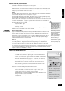
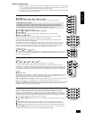
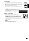
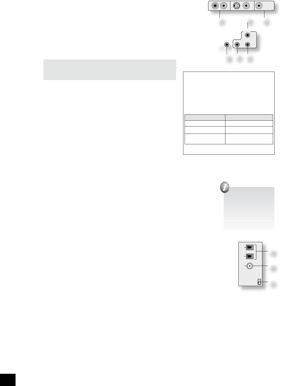
eq
ZONE 2 OUT.
This is the audio output for Zone 2. Connect these to a line level input on
your Zone 2 amplier.
do
ZONE 2 VIDEO OUT (Composite video connection).
This is the video output for Zone 2. Connect to your Zone 2 video display
using 75Ω low loss coaxial cable.
fk
IN ZONE 2.
This allows the AVR350 to be controlled remotely from Zone 2 via infrared
remote control. See the panel for connection information.
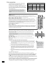
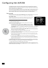
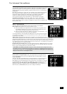
Connecting the AM and FM antennas
FM antenna
An FM antenna is required to receive VHF radio signals.
Although a FM ribbon antenna is supplied as an accessory to the AVR350, for optimal FM radio
reception a roof- or loft-mounted aerial is advised as this will give superior reception. (It is
recommended that any roof-top antenna is tted by an experienced contractor as a contractor
will be able to align your antenna to the nearest FM transmitter.)
In some areas cable radio may be available or, in an apartment building, a distributed antenna
system may be installed. In either of these cases you should have sockets in your home marked
FM or VHF (do not use those marked TV), which should be connected to the FM in socket
fr
of
the AVR350.
If you wish to use the supplied FM ribbon cable, mount this as high up as possible on a wall with
the ‘T’-elements positioned horizontally. Try each usable wall of the room to see which gives best
reception and use tacks or adhesive tape to secure the aerial in a T shape (note that no tacks
should come into contact with the internal wire of the aerial). When assembled (see box, right), the plug
on the ribbon cable should be connected to the FM in socket
fr
of the AVR350.
AM antenna
An AM antenna is required to receive AM/medium wave radio signals.
An AM loop antenna is supplied as an accessory with the AVR350. This should be attached to the AM
antenna inputs
fq
with one end connected to AM and the other to Ground (it does not matter which way
round this antenna is tted). Rotate the antenna to discover which position gives the best reception.
In areas of weak reception, or when the AVR350 is in use inside a steel framed building (such as an
apartment building), you can use a wire between 3 and 5 metres long to strengthen reception. Mount
this high up outside the building (if possible) and connect one end of this wire to the AM antenna input
in addition to the loop aerial supplied (do not disconnect the AM loop antenna).
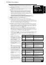
The AM tuning ‘step size’ needs to be set according to your location. This is done using the switch on the
rear panel
fs
: set it to 10kHz if you are in North America or 9kHz anywhere else. Note that this should
be set correctly even if you do not intend to use AM reception as it also alters some FM tuner settings for
use in North America.
AM
GND
FM
(USA) 10K
(EU) 9K
AM STEP
fq
fr
fs
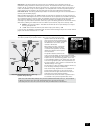
2) insert the spade
3) re-tighten the screws
MON
OUT
ZONE2
VIDEO
OUT
ZONE
2
REMOTE
IN
ZONE
2
IN
LOCAL
OUT
12V
TRIGGER
(Z1 & Z2)
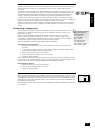
Zone 2 remote controller connection.
A receiver compatible with this connector
fk
is
available from Xantech (part no. 291-10). Please
contact a Xantech registered dealer for this part,
as ARCAM does not stock them.
See www.xantech.com for more information.
The 3.5mm jack plug for this connector is wired
as follows:
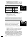
3.5mm stereo jack Function
Tip Signal
Ring 0V
Sleeve 12V,
30mA current-limited
This follows the Xantech standard for IR
transmission over wire.