


AVR250
E-8
AVR250
E-9
English
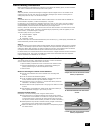
Connecting loudspeakers
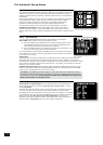
The red and black terminals on the back of the AVR250 are used to make the connections to the
loudspeakers. The speakers should be connected to the loudspeaker terminals, refering to the
labels on the rear-panel.
When connecting the speaker terminals of the ampli er with the terminals on the speakers make
sure that like polarities are matched (i.e., match “+” with “+” (usually red) and “–” with “–”
(usually black)). Mismatching of polarities will result in a weak central sound, unclear orientation
of the instruments and the sense of direction of the stereo being impaired.
There are two options for connecting the speaker cable to the ampli er:
Using bare wire ended leads:
1. Strip back the insulation on the wire to reveal about 2cm of conductor (the metal inside
the cable).
2. If the conductor is stranded, twist the strands together tightly to avoid loose strands making
contact with the adjacent terminals or the back panel.
3. Loosen the terminal by turning it anti-clockwise
4. Insert the twisted wire through the hole in the terminal.
5. Tighten by turning clockwise.
When making connections with stranded bare ended wires, take great care that no individual strands of
wire come into contact with the adjacent terminals or with the back panel. If this should happen, it will
cause a short circuit on the output of the ampli er and could damage the ampli er.
Using spade terminals:
1. Loosen the terminal by turning it anti-clockwise
2. Insert the spade connector under the terminal.
3. Tighten by turning clockwise.
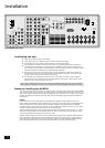
Speaker impedance
Before connecting loudspeakers to your AVR250 you must set the impedance switch on the rear to the
correct position (never adjust this switch with the power on or you may damage your speakers). If your
loudspeakers are rated at 6Ω or lower set the switch to the 4Ω position; if your loudspeakers are rated
higher than 6Ω, set the switch to the 8Ω position. This unit should only be used with loudspeakers with
an impedance rating above 4Ω.
Note that failure to set this switch correctly for your speakers may cause the ampli er to shut down due
to overheating.
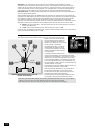
Zone 2 connections
The AVR250 allows independent routing and control of analogue audio and composite
video to a second room such as a kitchen, bedroom or lounge. This second room is known
as ‘Zone 2’.
For Zone 2, the AVR250 outputs a line-level audio signal taken from the stereo analogue
audio, and a composite video signal taken from the composite video input (for a given
source). The analogue inputs are required because there is no analogue-to-digital, DSP
processing or digital-to-analogue conversion available for Zone 2 signals. As the AVR250
does not convert video formats for Zone 2, a composite video signal must also be
connected from the source.
For these reasons, we recommend that source devices that have a digital connection are
also connected via the analogue inputs. High quality YUV/RGB and S-video sources should
also have their composite video outputs connected to the AVR250 for use in Zone 2.
NOTE: As a composite input is required for Zone 2, it may not be
possible to run your DVD player in progressive scan mode and to use
Zone 2 at the same time, unless your DVD player can output both
progressive scan and composite signals simutaneously.
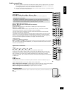
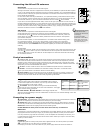
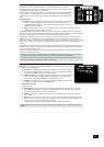
eq
ZONE 2 OUT.
This is the audio output for Zone 2. Connect these to a line level input on
your Zone 2 ampli er.
do
ZONE 2 VIDEO OUT (Composite video connection).
This is the video output for Zone 2. Connect to your Zone 2 video display
using 75Ω low loss coaxial cable.
fk
IN ZONE 2.
This allows the AVR250 to be controlled remotely from Zone 2 via infrared
remote control. See the panel for connection information.
MON
OUT
ZONE2
VIDEO
OUT
ZONE
2
REMOTE
IN
ZONE
2
IN
LOCAL
OUT
12V
TRIGGER
(Z1 & Z2)
Zone 2 remote controller connection.
A receiver compatible with this connector
fk
is
available from Xantech (part no. 291-10). Please
contact a Xantech registered dealer for this part,
as ARCAM does not stock them.
See www.xantech.com for more information.
The 3.5mm jack plug for this connector is wired
as follows:
3.5mm stereo jack Function
Tip Signal
Ring 0V
Sleeve 12V,
30mA current-limited
This follows the Xantech standard for IR
transmission over wire.
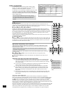
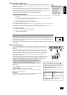
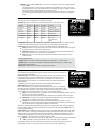
SPEAKER
IMPEDANCE
The speaker connectors
on the rear-panel are
labelled as follows:
FL - Front Left
FR - Front Right
CEN - Centre
RS - Right Surround
LS - Left Surround
RSB - Right Surr. Back
LSB - Left Surr. Back