


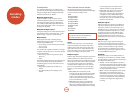
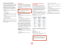
E-54
Zone2 and 3 control outputs
e AVR500, AVR600 and AV888 also allow remote
control from remote zones.
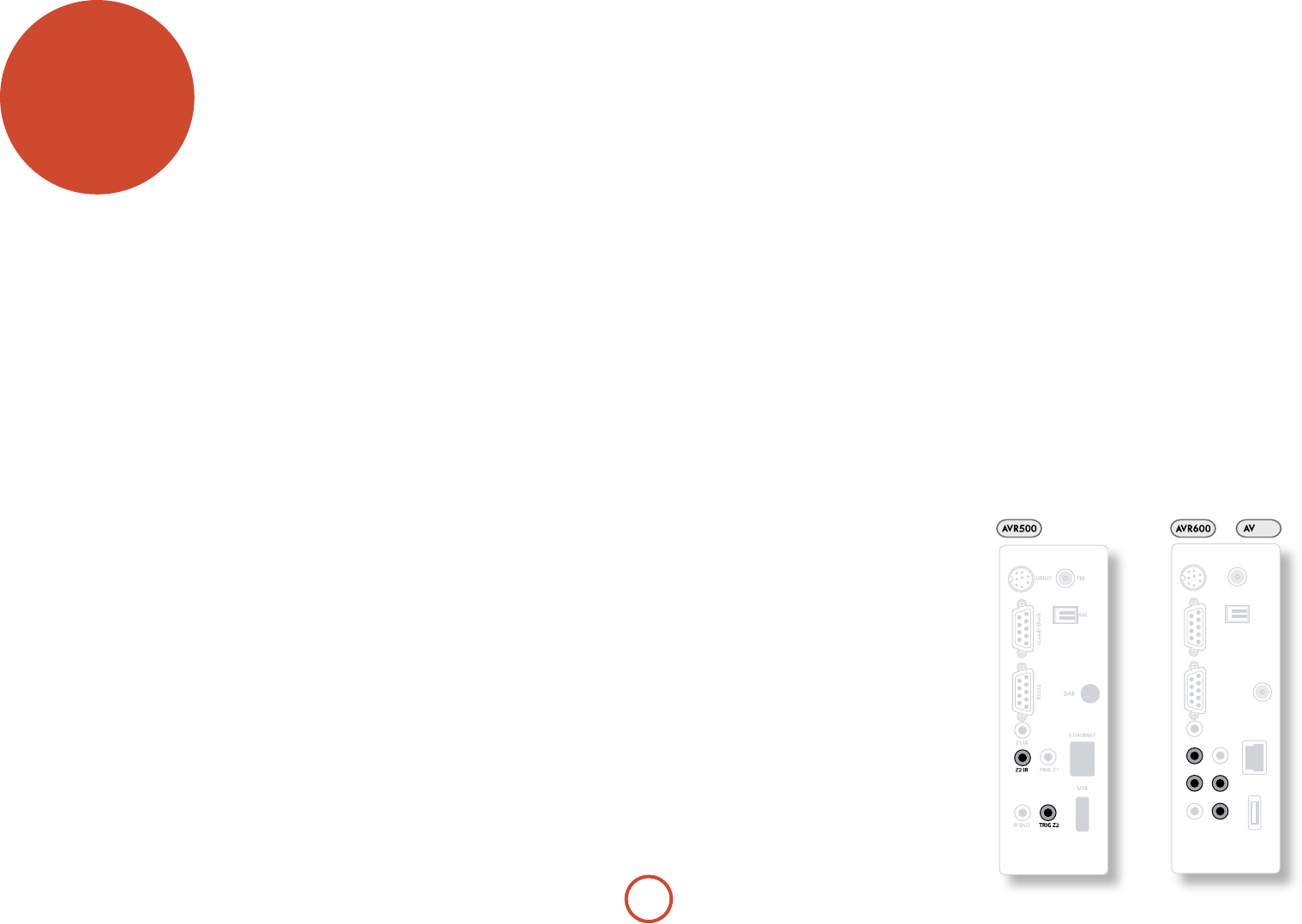
Z2 IR and Z3 IR
is allows the AVR500/AVR600/AV888 to be
controlled remotely from Zone2 (or Zone3) via Infra-
red remote control. Connect a remote IR receiver in
Zone2 (or Zone3) to allow control of the AVR500/
AVR600/AV888 from these listening/viewing areas.
For more information on remote IR receivers, see ‘Z1 IR’
on page 17.
TRIG Z2 and TRIG Z3
is allows the AVR500/AVR600/AV888 to remotely
switch on devices in Zone2 (or 3) when the appropriate
Zone is selected. For example you could set your
television in Zone2 to switch on when ‘Zone2’ is
selected on AVR500/AVR600/AV888.
For more information on triggers, see ‘Trigger
connectors’ on page 17. Please note that not all AV
devices have this feature, nor are triggers essential for
listening and viewing in a separate zone.
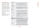
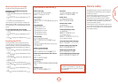
multi-room
set up
e AVR500, AVR600 and AV888 allow independent
routing and control of analogue audio, Composite and
S-Video to a separate set of equipment, typically used
for a second living space, e.g., bedroom or lounge. e
AVR600 and AV888 also allow a copy of the Zone2
analogue audio to be routed to and controlled in a third
living space, Zone3.
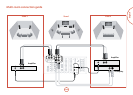
e connection guide on the facing page shows how the
AVR600 or AV888 is normally connected in a multi-
room installation.
Zone2
Zone2 receives only signals obtained by the AVR500,
AVR600 or AV888 from the analogue audio, Composite
and S-Video inputs. e analogue inputs are required
because there is no analogue-to-digital, digital-to-
analogue or DSP processing available for Zone2 signals
– the unit only converts video formats for Zone1.
For this reason, we recommend that in addition to any
digital connections, the Composite and/or S-Video
outputs from your source devices are connected to the
AVR500, AVR600 or AV888.
Video outputs
e Z2 S-Video and/or Composite output connectors of
the AVR500/AVR600/AV888 should be connected to
the analogue video inputs (usually labelled SVIDEO IN or
COMPOSITE VIDEO IN) of the display device in Zone2.
If you wish to make an HDMI connection to Zone 2,
you must accept the limitations of the AVR500/AVR600/
AV888 video processing system.
HDMI OUT 1 and OUT 2 both carry the same signals (as
there is only one video processing engine) and are
primarily intended for use in Zone 1. Full HDMI video
functionality in Zone 2 can only be achieved if Zone 1 is
not being used at the same time.
If Zone 1 is being used at the same time as Zone 2,
Zone 2 must follow the Zone 1 source selection if you
wish to receive HDMI signals in Zone 2. Zone 2 must
also be the same video resolution as Zone 1. If you wish
to watch a dierent source in Zone 2 than is currently
showing over HDMI in Zone 1, Zone 2 will be forced to
use the analogue video connections into and out of the
AVR500/AVR600/AV888.
Due to the complications of using HDMI in Zone 2
we recommend the use of analogue video connections
instead, particularly as it is not possible to apply audio
lip sync to Zone 2 audio to compensate for video
processing delays.
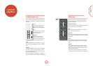
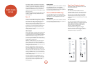
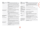
SIRIUS
AM
DAB
FM
ETHERNET
Z2 IR
IR OUT
Z1 IR
Z3 IR
rLead/rDockRS232
USB
TRIG Z1
TRIG Z2
TRIG Z3
Audio outputs
e Z2 OUT, R and L phono sockets should be connected
to the analogue audio inputs (Usually labelled
ANALOGUE AUDIO IN) of the Zone2 display device, or
to the inputs of an additional stereo power amplier in
Zone2 (for example, the Arcam P38).
Zone3 (AVR600/AV888 only)
A line-level signal from the stereo analogue audio is
available for Zone3. is is a copy of the Zone2 audio
signal, but has its own independent volume control.
Audio outputs
e Z3 OUT, R and L phono sockets should be connected
to the inputs of an additional stereo power amplier in
Zone3 (for example, the Arcam P38).
888